My diy-efi project
This version is rather simple, and does not include
any fancy functions.
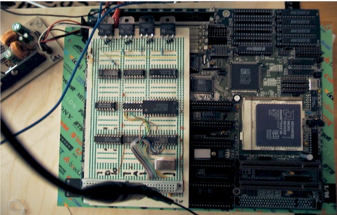
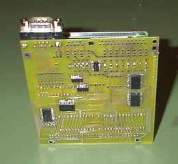
My system includes two boards, one standard PC-motherboard,
the one board, which is selfmade, connected via ISA-bus.
My board has multi-channel A/D-converter (ADC0844),
timers (8254), injector drivers, digital IO-ports and
some logic needed.
Most of the mechanical parts are from bosch L-Jetronic
system, used in IS-Sierra.
This version does control only injection, not ignition.
The system is currently mounted to my Ford Sierra 2.0 turbo. More information about Sierra here.
All the software running the EFI is written with
assembly-language. The software itself has been
burned to a flash-rom chip on the place of motherboard's
bios-chip.
Some versions were also booted from floppy! After turning
on the car, you had to wait about 15sec, while system was
booting, before you could start the engine! :)
I also have written a software used to configure the EFI.
I am able to modify the fuel injection curves, and lots
of other parameters with the software. I have curves for
every 100RPM's.
Screen capture from configuration software: 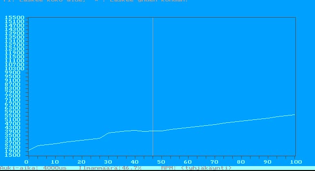
I have used potentiometer at cabin, which controls mixture, so that adjusting the engine is littlebit easier. I also have lambda-sensor mounted to exhaust, but it isn't used yet.
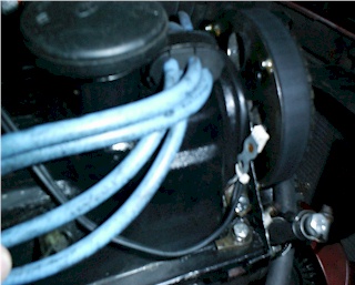
Four small magnets are glued to end of camshaft (picture), passing Hall-Effect
sensor.
Hall-effect trigger signal is connected to IRQ-line on
motherboard, causing IRQ occur 4 times per camshaft turn.
When IRQ occurs, every other time (one crankshaft turn) following is done:
- Injectors are opened.
- RPM is calculated from time between interrupts, using special look-up table.
- Values from A/D sensors are read. (AirFlowMeter, Throttle position, temp, etc..)
- Pulse width (injector open time) is calculated, using several tables. If RPM is very low (engine is being started), pulse width is static. If throttle is fully closed, and RPM is high, injectors are not opened to save fuel.
- Timer1 is set with injector-open time, calculating down.
- When timer1 reaches zero, injectors are closed, completely by hardware.
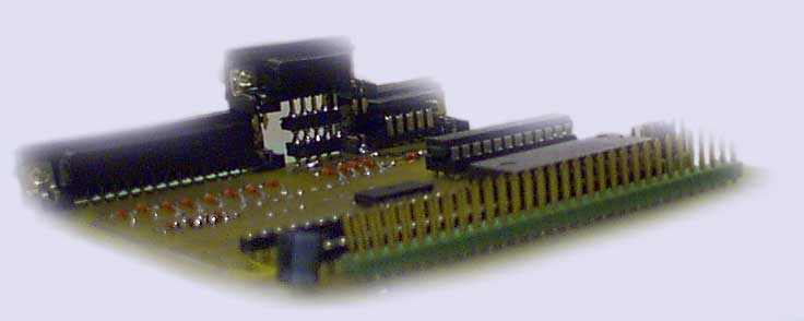
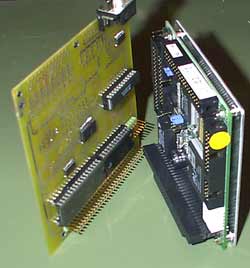
Few pictures about project (quite early stage), in
"Professional" testing environment:
This version used 486-processor
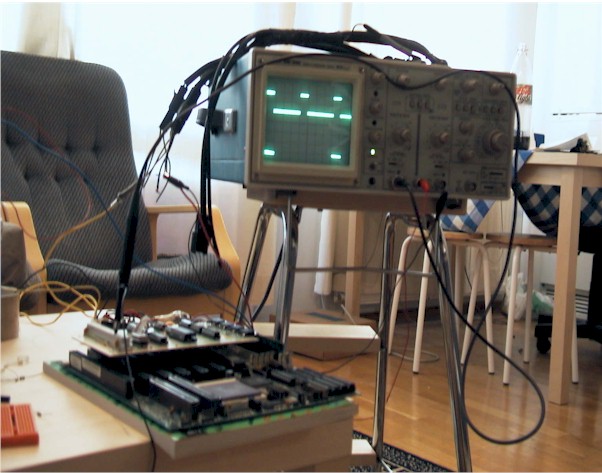
Click to enlarge!
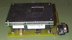
Pentium-Version mounted to Sierra at summer 2000
looked like this: 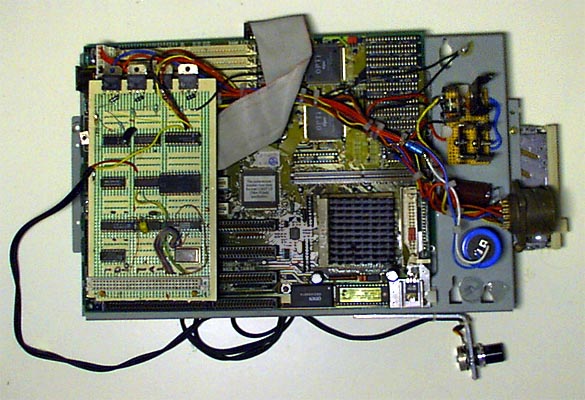
Second version of my ECU has these features:
- Integrated flash-rom, where program and settings are, programmable via serial-port
- Digital ignition (distributorless, direct ingition possible)
- Controls 4 fuel injectors sequently
- 8 Analog inputs, can be used for sensors (MAP,TEMP,THROTTLE POS,LAMBDA etc..)
- 8 Digital outputs + 4 for injectors
- 8 Digital inputs + 2 for camshaft positions
- Datalogging functions, collected to boards own RAM from where downloaded to PC, or directly to PC console.
- Smaller size and connector to connect directly to PC/104 standard motherboard.
- Manufactured using SMD-technology.
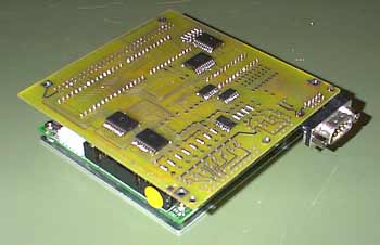
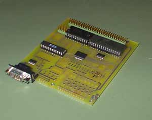
PCB design looks like this: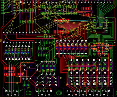
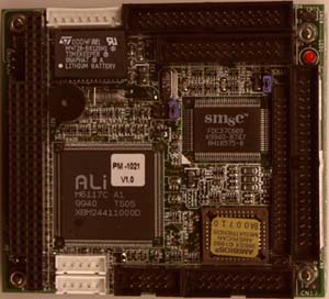
Motherboard to be used with version 2.0 (10cm x 10cm):
FIRST PICTURES OF VER.2 ECU:
Year has changed, and I still have been very busy.. I have done only some minor modifications to my project-car, not this injection-system at all. :(
11.12.2001
I have been busy with other projects, and haven't got time to do this.. :(
I should continue the project now, or else I'll get very busy getting the car in shape before next summer..
15.10.2001
Version 2 should have been working in Sierra during summer 2001, but due lack of time I coudn't get it working as well as it should have. It picked too much interference from car, and was not stable enough. I got the car running, but the system jammed after running a while, and it had to be restarted. During the winter I'll get it working..
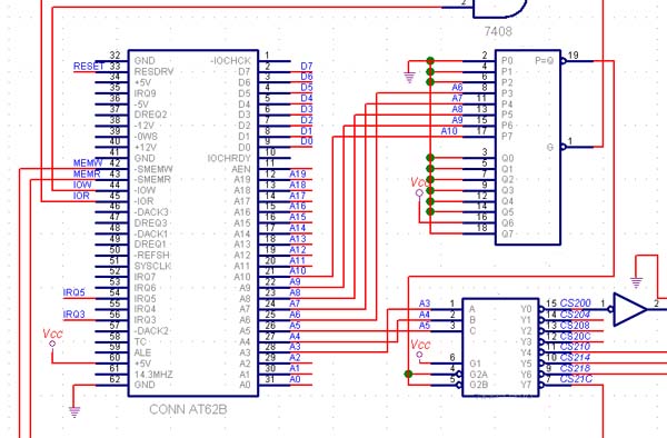
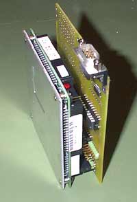
Here is the first one, showing some interfacing with AT-bus: